Ask For A Quick Quote
We will contact you within one working day. Please pay attention to your email.
Request a Sample
With the mission of “Smart Manufacturing - Global Delivery”, we help our customers shorten the time-to-market and optimize the supply chain cost through continuous technology iteration and digital upgrading. We look forward to working with you to define the future of electronic manufacturing!
- Technology Driven Intelligent Manufacturing
- Full-process quality control
- In-depth industry experience
- Agile Service Network
UAV PCB Assembly
One-stop PCBA/EMS Intelligent Manufacturing Solution
UAV PCB Assembly
The Role of PCBs in UAV
Printed Circuit Boards (PCBs) are the backbone of modern UAV systems, providing the essential infrastructure for power distribution, signal processing, and communication. In UAVs, PCBs ensure that all onboard electronics operate reliably and efficiently, even under challenging environmental conditions.
1. Power Management and Distribution
PCBs manage power from the UAV’s battery to various subsystems such as motors, sensors, GPS modules, and communication units.
They integrate voltage regulation and current control to prevent damage to sensitive components.
High-current PCBs are often used for motor control circuits in propulsion systems.
2. Control Systems Integration
Flight control boards, built on high-precision PCBs, process input from sensors and issue commands to actuators.
Microcontrollers or embedded processors on these PCBs execute real-time flight algorithms for stability and navigation.
Connections for gyroscopes, accelerometers, and magnetometers are integrated directly onto the PCB.
3. Communication Systems
PCBs in UAVs host radio transmitters, receivers, and antennas for data link communication between the UAV and ground control.
RF (radio frequency) PCBs are designed with low-loss materials to ensure stable and long-range connectivity.
They support telemetry data, live video streaming, and command signals.
4. Sensor Integration
UAVs rely on PCBs to connect and process data from cameras, LiDAR, infrared sensors, and GPS modules.
Multi-layer PCBs allow for compact layouts that can integrate multiple sensor interfaces without signal interference.
5. Signal Processing and Data Handling
High-speed PCBs are used in imaging systems to process high-resolution video or mapping data in real time.
They enable onboard AI modules to process data for tasks like obstacle detection, object tracking, or autonomous navigation.
6. Reliability and Environmental Resistance
UAV PCBs are designed to withstand vibration, temperature fluctuations, and humidity.
Special coatings (conformal coatings) protect PCBs from dust and moisture during outdoor operations.
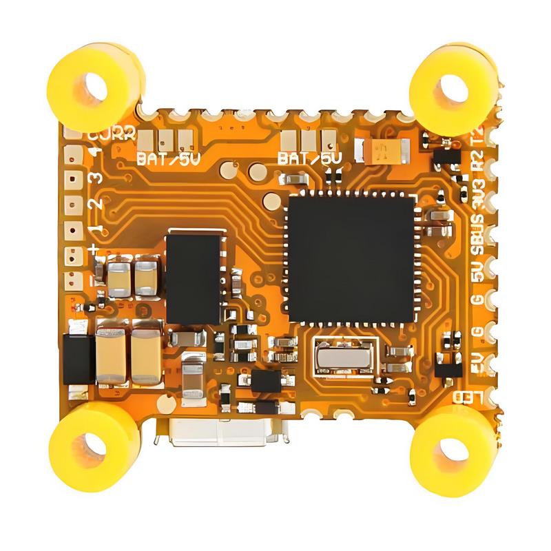
Key Components of UAV PCB Assembly
UAV PCB assemblies bring together a variety of electronic components to power, control, and communicate with unmanned aerial vehicles. Each component plays a critical role in ensuring efficient operation, stability, and performance.
1. Microcontrollers and Processors
Serve as the “brain” of the UAV, executing flight control algorithms and coordinating subsystems.
Examples: ARM-based MCUs, FPGAs for high-speed processing.
2. Power Management Units (PMUs)
Regulate and distribute power from the UAV’s battery to motors, sensors, and communication modules.
Include voltage regulators, DC-DC converters, and power distribution networks.
3. Motor Control Circuits (ESCs)
Electronic Speed Controllers (ESCs) manage motor speed, direction, and braking.
Designed on high-current PCBs to handle the load of propulsion systems.
4. Communication Modules
Facilitate real-time data exchange between UAV and ground control.
Include RF transceivers, Wi-Fi modules, GPS receivers, and antenna circuits.
5. Sensor Interfaces
Connect and manage various onboard sensors such as IMUs (gyroscopes, accelerometers), barometers, magnetometers, cameras, and LiDAR.
Often integrated via multi-layer PCB traces to minimize noise and interference.
6. Data Storage Units
Store flight logs, sensor data, and media from onboard cameras.
Use embedded memory chips or removable storage modules like microSD slots.
7. Thermal Management Features
Heat sinks, thermal vias, and copper pours to dissipate heat from high-power components like processors and ESCs.
8. Protection and Safety Circuits
Overcurrent protection, reverse polarity protection, and ESD suppression to safeguard sensitive electronics.
Materials and Technologies for UAV PCB Assembly
UAV PCB assemblies require carefully selected materials and advanced manufacturing technologies to ensure lightweight, high-performance, and reliable operation under demanding conditions.
1. PCB Base Materials
FR-4 Epoxy Glass Laminate – Standard choice for cost-effective UAV circuits with good mechanical strength.
High-Frequency Laminates (e.g., Rogers, Taconic) – Used in RF and communication circuits for low signal loss and stable dielectric properties.
Aluminum-Core PCBs – Provide enhanced heat dissipation for high-power applications such as ESCs.
Flexible & Rigid-Flex PCBs – Allow compact designs and withstand vibration by replacing multiple connectors with bendable circuits.
2. Conductive Materials
Copper Foil – Standard conductor for PCB traces, available in various thicknesses (1 oz, 2 oz, or more for high-current lines).
Surface Finishes – ENIG (Electroless Nickel Immersion Gold), HASL, or Immersion Silver to ensure solderability and oxidation resistance.
3. Assembly Technologies
Surface Mount Technology (SMT) – Enables high-density component placement for compact UAV boards.
Through-Hole Technology (THT) – Used for components requiring mechanical strength, such as connectors and large capacitors.
Mixed Technology Assembly – Combines SMT and THT for optimal performance and durability.
4. Special Design & Manufacturing Technologies
High-Speed PCB Design – For data processing and video transmission systems.
RF PCB Design – Ensures minimal signal loss for communication modules.
Thermal Management Techniques – Use of thermal vias, copper pours, and aluminum cores to manage heat from processors and motor drivers.
Conformal Coating – Protects against moisture, dust, and chemical exposure during outdoor operation.
Vibration-Resistant Soldering – Reinforced joints and adhesive underfills for components exposed to mechanical stress.
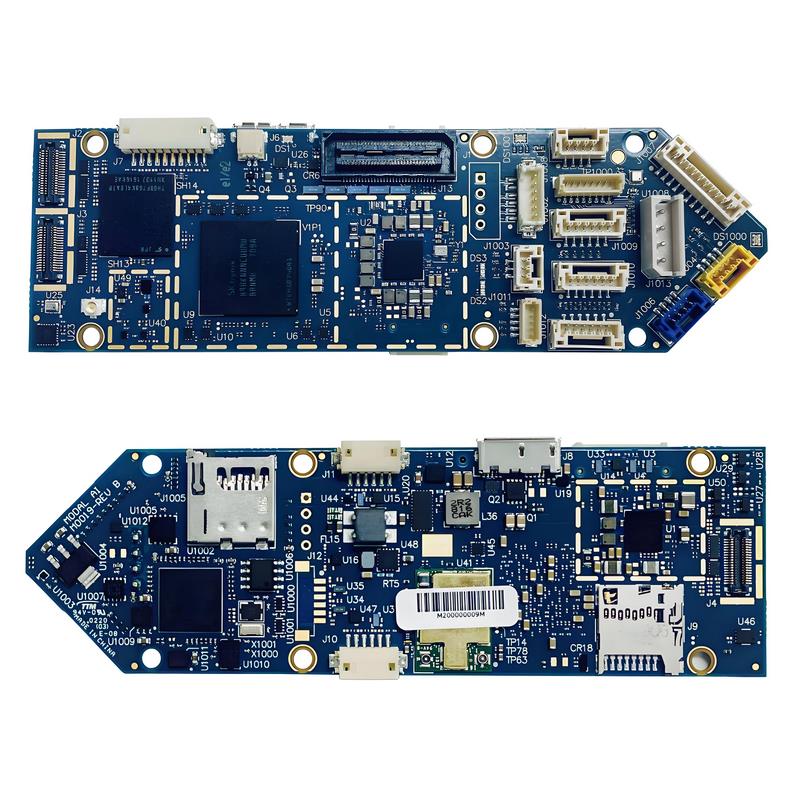
UAV PCB Assembly Process
The assembly of UAV PCBs requires precision manufacturing and strict quality control to ensure performance, reliability, and safety during flight. Below is a step-by-step overview of the process.
1. Design and Prototyping
Create the PCB layout, integrating flight control, power, communication, and sensor circuits.
Simulate electrical performance and thermal behavior to verify design feasibility.
Produce prototypes for initial functional testing.
2. Material Selection
Choose suitable base laminates (FR-4, high-frequency materials, aluminum-core, or rigid-flex).
Select copper thickness, surface finish, and protective coatings based on UAV requirements.
3. PCB Fabrication
Imaging and Etching – Transfer circuit patterns onto copper-clad boards and etch away excess copper.
Drilling – Create holes for through-hole components and vias.
Plating – Apply copper plating to vias and through-holes for conductivity.
Surface Finishing – Use ENIG, HASL, or immersion silver to prepare solderable surfaces.
4. Component Procurement and Inspection
Source high-quality microcontrollers, sensors, RF modules, ESC components, and connectors.
Perform incoming quality inspection to verify specifications and prevent counterfeit parts.
5. Component Placement
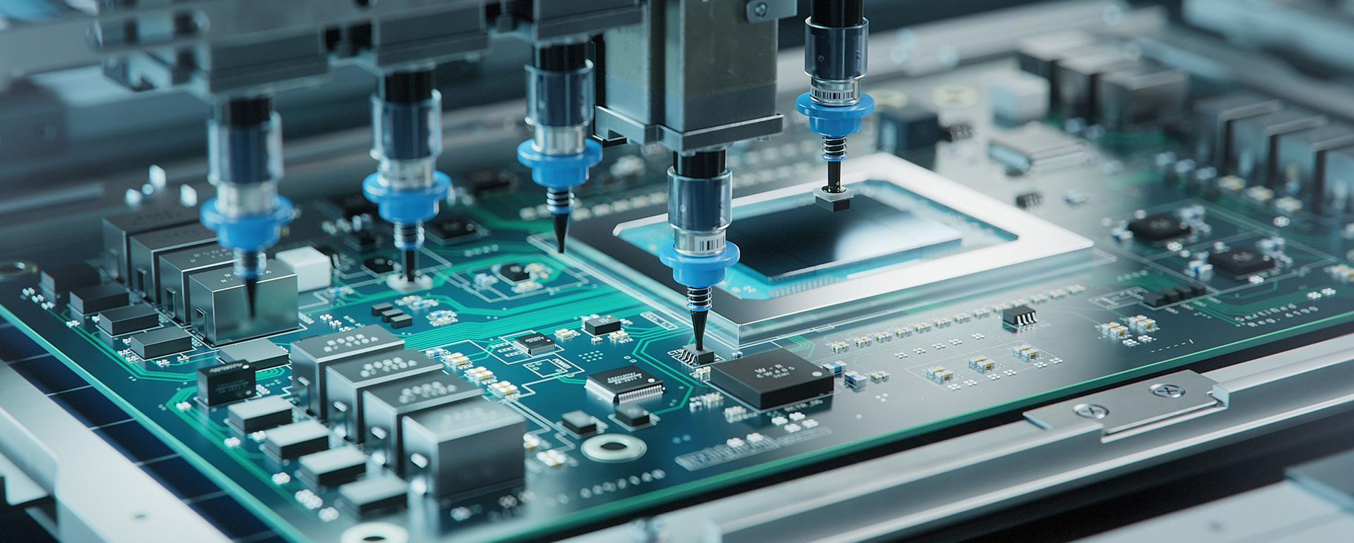
Surface Mount Technology (SMT) – Place SMD components using high-speed pick-and-place machines.
Through-Hole Technology (THT) – Install connectors, large capacitors, or structural components requiring mechanical strength.
6. Soldering
Reflow Soldering – Used for SMT components, where solder paste is melted in a controlled oven process.
Wave Soldering / Selective Soldering – Applied to through-hole components for strong joints.
7. Cleaning and Coating
Remove flux residues and contaminants from the PCB.
Apply conformal coating to protect against vibration, moisture, and dust.
8. Testing and Quality Assurance
Functional Testing – Verify that all circuits operate according to design.
In-Circuit Testing (ICT) – Check for shorts, opens, and component placement errors.
Environmental Stress Testing – Simulate vibration, temperature changes, and humidity to ensure field reliability.
9. Final Assembly and Integration
Mount the PCB into the UAV chassis and connect to motors, sensors, and communication systems.
Perform full system testing, including flight simulations, before deployment.
Future Implications of UAV PCB Assembly
As UAV applications expand across commercial, industrial, and defense sectors, the demand for more advanced, reliable, and miniaturized PCB assemblies will continue to grow. Several trends are set to shape the future of UAV PCB assembly:
1. Increased Miniaturization and Integration
Trend: UAVs will require smaller, lighter PCBs with higher component density to extend flight time and payload capacity.
Impact: Growth in multi-layer rigid-flex PCBs and embedded component technology to reduce weight and size without sacrificing performance.
2. Advanced Materials for Performance and Durability
Trend: Development of high-frequency, high-temperature, and vibration-resistant PCB materials.
Impact: Improved signal integrity for long-range communications and enhanced reliability in extreme environments.
3. AI and Edge Computing on Board
Trend: Integration of AI processors directly onto UAV PCBs for real-time image recognition, navigation, and decision-making.
Impact: Reduced dependence on ground-based processing, enabling fully autonomous UAV missions.
4. Enhanced Power Management
Trend: Adoption of high-efficiency power distribution systems and energy harvesting technologies.
Impact: Longer flight durations, better battery utilization, and improved performance for power-hungry payloads.
5. IoT and Swarm Communication
Trend: Development of PCBs optimized for mesh networking and swarm coordination.
Impact: UAV fleets operating collaboratively for mapping, search and rescue, or agricultural monitoring.
6. Sustainable Manufacturing Practices
Trend: Eco-friendly PCB manufacturing with recyclable substrates, lead-free soldering, and reduced chemical waste.
Impact: Lower environmental footprint and compliance with stricter global environmental regulations.
7. Increased Reliability and Self-Healing Electronics
Trend: Research into self-healing PCB materials and predictive maintenance sensors embedded in boards.
Impact: Reduced downtime and extended UAV lifespan in mission-critical applications.
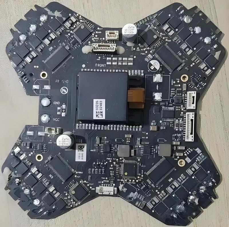
Conclusion
PCBs are the central nervous system of UAVs, enabling precise control, efficient power management, high-speed communication, and seamless integration of sensors and payloads. Advances in materials, assembly technologies, and design methodologies are making UAV PCBs more compact, reliable, and capable than ever before.
As UAV applications continue to diversify — from aerial photography and mapping to industrial inspection and defense — the demand for high-performance PCB assemblies will only intensify. Manufacturers who embrace innovation, ensure rigorous quality control, and adapt to emerging technologies will be well-positioned to lead in the next generation of UAV development.
Ready to Elevate Your PCB Projects to New Heights?
Whether you’re developing high-performance UAVs for industrial, commercial, or defense applications, precision-engineered PCB assemblies are the foundation of success. Our expertise in advanced materials, high-density layouts, and rigorous quality assurance ensures your UAVs perform reliably — even in the most demanding conditions.
Partner with us to transform your concepts into flight-ready solutions. From design and prototyping to full-scale production, we deliver PCB assemblies that help your UAVs soar higher, last longer, and achieve more.


