


Ask For A Quick Quote
We will contact you within one working day. Please pay attention to your email.
Request a Sample
With the mission of “Smart Manufacturing - Global Delivery”, we help our customers shorten the time-to-market and optimize the supply chain cost through continuous technology iteration and digital upgrading. We look forward to working with you to define the future of electronic manufacturing!
- Technology Driven Intelligent Manufacturing
- Full-process quality control
- In-depth industry experience
- Agile Service Network

New Energy and Automotive PCB Assembly
One-stop PCBA/EMS Intelligent Manufacturing Solution


New Energy and Automotive PCB Assembly
Understanding New Energy Vehicle (NEV) PCBs
New Energy Vehicles (NEVs), including electric vehicles (EVs), hybrid electric vehicles (HEVs), and fuel cell vehicles, rely heavily on specialized PCBs (Printed Circuit Boards) to support their advanced electronic systems. Unlike traditional vehicles, NEVs require high-reliability, high-power, and thermally optimized PCBs to ensure safe and efficient performance under demanding operating conditions.
Key Roles of PCBs in NEVs:
Battery Management Systems (BMS): Monitor and balance battery cells, track voltage, current, and temperature.
Power Conversion Systems: Support inverters, DC-DC converters, onboard chargers (OBCs), etc.
Motor Control Units (MCUs): Handle real-time motor operation and torque control.
Vehicle Control Units (VCUs): Centralized control of communication between subsystems.
ADAS and Infotainment Systems: Enable driver assistance, navigation, connectivity, and in-car experiences.
Key Features of NEV PCBs:
High Voltage and Current Tolerance: Required for handling battery packs, inverters, and power electronics.
Excellent Thermal Management: Use of thick copper layers, metal core PCBs (MCPCBs), and thermal vias.
Reliability under Harsh Conditions: Must withstand vibration, moisture, temperature extremes, and long operating cycles.
Compliance with Automotive Standards: Must meet stringent certifications such as IATF 16949, ISO 26262 (functional safety), and AEC-Q200.
NEV PCBs play a crucial role in ensuring vehicle safety, energy efficiency, and intelligent control. As the global shift toward electrification accelerates, demand for advanced, durable, and precisely assembled PCBs continues to grow — making them a backbone of the new energy automotive industry.
Key Components of New Energy Vehicles
New Energy Vehicles (NEVs)have someunique components that ensure efficient operation. Here are the key components:
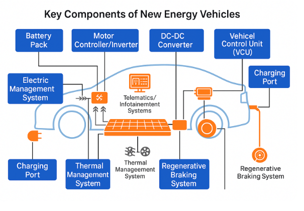
Main Power Control Systems in New Energy Vehicles
|
System |
Function / Description |
|
Battery Management System (BMS) |
Monitors and manages the health, charging, discharging, and temperature of the battery pack to ensure safe and efficient operation. |
|
Motor Controller / Inverter |
Converts DC from the battery into AC to drive the electric motor; controls speed, torque, and direction of the vehicle. |
|
Vehicle Control Unit (VCU) |
Serves as the “brain” of the powertrain; coordinates power delivery by managing the BMS, inverter, motor, and other subsystems. |
|
On-Board Charger (OBC) |
Converts external AC input into DC to charge the vehicle's battery; manages voltage regulation and charging profiles. |
|
DC-DC Converter |
Steps down high-voltage DC from the battery pack to lower-voltage DC for auxiliary systems (e.g., lighting, infotainment, ECU). |
|
Thermal Management System |
Maintains optimal temperatures for the battery, motor, and power electronics to ensure performance and extend lifespan. |
|
Energy Recovery System |
Manages regenerative braking, converting kinetic energy back into electrical energy for battery storage. |
Applications of New Energy Vehicle PCBs
Printed Circuit Boards (PCBs) in new energy vehicles are crucial for numerous applications. These boards control various electronic systems, ensuring the vehicle operates efficiently and safely. Here are some key applications of new energy vehicle PCBs:
Unique Features of New Energy Vehicle PCBs
New energy vehicle PCBs are designed to meet the specific demands of electric vehicles. Here are their key features:
1. High Voltage and High Current Tolerance
NEV PCBs must handle high-voltage systems (typically 400V–800V for EVs).
Require thicker copper layers (up to 3oz or more) and wider traces to support high current flow, especially in battery management systems (BMS) and motor controllers.
2. Excellent Thermal Management
NEV power components generate significant heat.
Use of metal-core PCBs (MCPCBs), ceramic substrates, and thermal vias for efficient heat dissipation.
Integration with liquid cooling or heat sinks in critical zones.
3. High Reliability in Harsh Environments
Must endure extreme temperature fluctuations, moisture, vibration, and dust.
Require automotive-grade materials, conformal coating, and robust encapsulation.
4. High-Frequency and High-Speed Signal Capability
NEVs include advanced ADAS (Advanced Driver Assistance Systems), autonomous driving tech, and wireless communication modules.
PCBs often use high-frequency laminates (e.g., Rogers, Taconic) to support RF and millimeter-wave signals.
5. Multi-Layer and Rigid-Flex Designs
Need to accommodate dense, space-constrained layouts (e.g., in compact control units).
Use of multi-layer and rigid-flex PCBs to integrate signal, power, and control circuits in 3D formats.
6. Functional Integration
NEV PCBs integrate various systems like:
Battery Management System (BMS)
Inverter/Converter modules
Onboard Chargers (OBC)
Vehicle Control Units (VCU)
Emphasis on modular design and embedded components for efficiency and compactness.
7. Electromagnetic Compatibility (EMC)
EV power electronics generate significant electromagnetic noise.
PCBs are designed with EMI shielding, ground planes, filters, and optimized trace layout to reduce interference.
8. Strict Quality and Testing Standards
Must meet standards like IATF 16949, ISO 26262 (functional safety), and AEC-Q200 for electronic components.
Undergo in-circuit testing (ICT), functional testing (FCT), thermal cycling, X-ray, and environmental stress screening (ESS).
Materials and Technologies for New Energy Automotive PCB Assembly
The rapid evolution of new energy vehicles (NEVs) demands innovative materials and technologies in PCB assembly to meet higher performance, reliability, and efficiency standards.
Materials for New Energy Vehicle PCB Assembly
1. Base Substrate Materials
FR-4 (High-Tg & Halogen-free): Common but upgraded for better thermal stability.
Polyimide: Used in flex and rigid-flex PCBs for high heat resistance.
Metal Core (MCPCB): Aluminum or copper core for thermal conductivity, ideal for power modules.
Ceramic Substrates (AlN, Al₂O₃): Exceptional thermal performance and electrical insulation, often used in inverters and power control modules.
2. Copper Foil
Heavy Copper (≥2 oz/ft²): Supports high current flow; common in powertrain systems.
Embedded Copper Coin Technology: Improves heat dissipation and current carrying capacity.
3. Solder Mask and Surface Finish
High-temperature resistant solder masks: Withstand reflow cycles and operating heat.
ENIG (Electroless Nickel Immersion Gold): Preferred for fine-pitch and high-reliability.
OSP, ImAg, or ENEPIG: Alternative finishes, chosen based on assembly and cost needs.
4. Conformal Coatings
Protect PCBs from moisture, salt spray, chemicals, and vibration.
Common coatings: Acrylic, Polyurethane, Silicone, or Parylene.
Advanced Technologies in NEV PCB Assembly
1. High-Density Interconnect (HDI)
Allows compact design with fine pitch, used in BMS and control units.
Laser drilling, microvias, and sequential lamination enable advanced layering.
2. Embedded Components
Passive or active components embedded within the PCB.
Reduces size and increases reliability by minimizing interconnects.
3. Rigid-Flex Technology
Combines rigid and flexible PCBs in a single design.
Ideal for space-constrained modules like dashboard electronics or sensor units.
4. Selective Soldering and Reflow
Precise soldering techniques suited for mixed technology boards (SMD + THT).
Ensures thermal control during soldering of sensitive automotive-grade components.
5. Automated Optical and X-Ray Inspection (AOI / AXI)
Guarantees solder joint integrity, especially in BGA, LGA, and QFN packages.
AXI is essential for double-sided and high-layer boards.
6. Functional and In-Circuit Testing (FCT/ICT)
Ensures performance and safety compliance.
Often integrated with vehicle simulation environments for real-world testing.
7. Thermal Simulation and Reliability Modeling
Use of thermal simulation software (e.g., ANSYS, FloTHERM) in design phase.
Helps predict hot spots, failure points, and guides material selection.
Design and Prototyping Process for New Energy Vehicle PCBs
1. Requirements Analysis
Define system architecture (e.g., Battery Management System, Motor Control, Charging Module).
Analyze:
Voltage/current requirements
Thermal management needs
Space constraints
EMC compliance
Automotive safety standards (ISO 26262, AEC-Q200)
2. Schematic Design
Electrical design using CAD tools (e.g., Altium Designer, OrCAD).
Careful component selection with automotive-grade certifications.
Redundancy and fail-safe circuitry for critical systems (e.g., VCU or BMS).
3. PCB Stack-Up and Layer Planning
Choose appropriate layer count (often 6–12 layers or more for NEVs).
Plan for:
Power and ground plane separation
Signal integrity
Thermal via placement
High-current copper routing
4. PCB Layout Design
Precise component placement to minimize thermal and EMI issues.
Use differential pair routing and impedance control for high-speed signals.
Place thermal reliefs, heat sinks, or metal cores in high-power zones.
Incorporate test points, edge connectors, and mounting holes as needed.
5. Thermal and Signal Simulation
Use simulation tools like:
ANSYS, HyperLynx, or FloTHERM
Analyze:
Heat dissipation
Voltage drop
Signal integrity
EMC performance
Iterate design before prototype fabrication.
6. Gerber Generation and DFM Review
Generate Gerber, BOM, pick & place, and netlist files.
Conduct DFM (Design for Manufacturability) and DFT (Design for Testability) checks.
Validate with PCB fabricator and EMS provider.
7. Prototype Fabrication
Choose appropriate material: FR-4 High Tg, Polyimide, Aluminum Core, or Ceramic.
Manufacture a limited prototype batch (e.g., 5–20 pcs).
Utilize quick-turn PCB services for fast validation.
8. PCB Assembly (PCBA)
Use automated SMT assembly with automotive-grade solder paste.
Apply selective soldering, BGA reflow, and AOI/AXI inspection.
Apply conformal coating for protection if needed.
9. Testing and Validation
Perform:
In-Circuit Test (ICT)
Functional Test (FCT)
Power cycling and thermal shock
Environmental stress screening (ESS)
Simulate actual vehicle operation conditions.
10. Prototype Review and Iteration
Analyze test results and collect feedback.
Revise design to fix issues such as:
Overheating
Noise coupling
Component failure
Prepare for pilot production after successful validation.
Key Considerations
Compliance: Meet automotive regulations (IATF 16949, ISO 26262).
Documentation: Maintain thorough design logs, change records, and test results.
Traceability: Use barcode/QR code tracking for each prototype board.
Conclusion
As the automotive industry shifts toward electrification and intelligent mobility, New Energy Vehicle PCBs are becoming increasingly critical in enabling safe, efficient, and high-performance systems. From power control and battery management to autonomous driving and connectivity modules, the design and assembly of NEV PCBs demand advanced materials, robust technologies, and strict quality standards.
The integration of high-voltage tolerance, thermal management, compact multilayer structures, and automotive-grade reliability ensures these PCBs can withstand the rigorous demands of next-generation vehicles. By following a well-structured process—from initial design and simulation to prototyping and testing—manufacturers can accelerate innovation while meeting safety and regulatory requirements.
Embracing cutting-edge PCB technologies will not only improve the efficiency and longevity of NEVs but also drive the future of sustainable, intelligent transportation.
Ready to Elevate Your PCB Projects to New Heights?
Whether you're developing cutting-edge new energy vehicles, advanced AIoT systems, or high-reliability industrial electronics, partnering with a trusted PCB assembly expert can accelerate your innovation and ensure long-term success.
At every stage—from concept and prototyping to full-scale production—we bring:
• Precision Engineering
• Advanced Manufacturing Technologies
• Stringent Quality Control
• Scalable, Turnkey Solutions
Let us help you transform your ideas into high-performance, future-ready products.
Contact us today to discuss your project requirements and discover how we can support your next breakthrough.
Request A Quote
Please feel free to contact us at any time, and we will wholeheartedly provide you with the highest quality service and support.